Engineering design
Engineering design concerns the process of creating solutions in the form of technical systems for problems. The design space is spanned by needs, requirements, and constraints. These can be set by material, technological, economic, legal, environmental and human related considerations.
An important step in the translation of needs, requirements and constraints into technical solutions is the design of the system architecture. The architecture of a system has a significant impact on its performance, e.g., reliability, availability, maintainability, and life cycle costs. Moreover, insight into the system's architecture is required to estimate the impact of (re-)design decisions. That is, the designs of system components are usually dependent on one another. As such, design choices with respect to one component may affect the design of other components. Overlooked dependencies often cause costly and lengthy design iterations.
As systems become increasingly complex the chance on overlooked dependencies increases exponentially. Therefore, engineers need methods to structure, visualize, and analyze needs, requirements, and constraints. This is exactly what Ratio CASE aims to offer. Our methods and tools aim at supporting engineers to reduce the chance on overlooked dependencies and enable them to develop better systems in less time and at fewer costs.
Engineering design process
In the literature on can find many models of the engineering design process. The figure below is a schematic representation of the design process which combines the V-model1, spiral model2 and design phases3 of Pahl and Beitz.
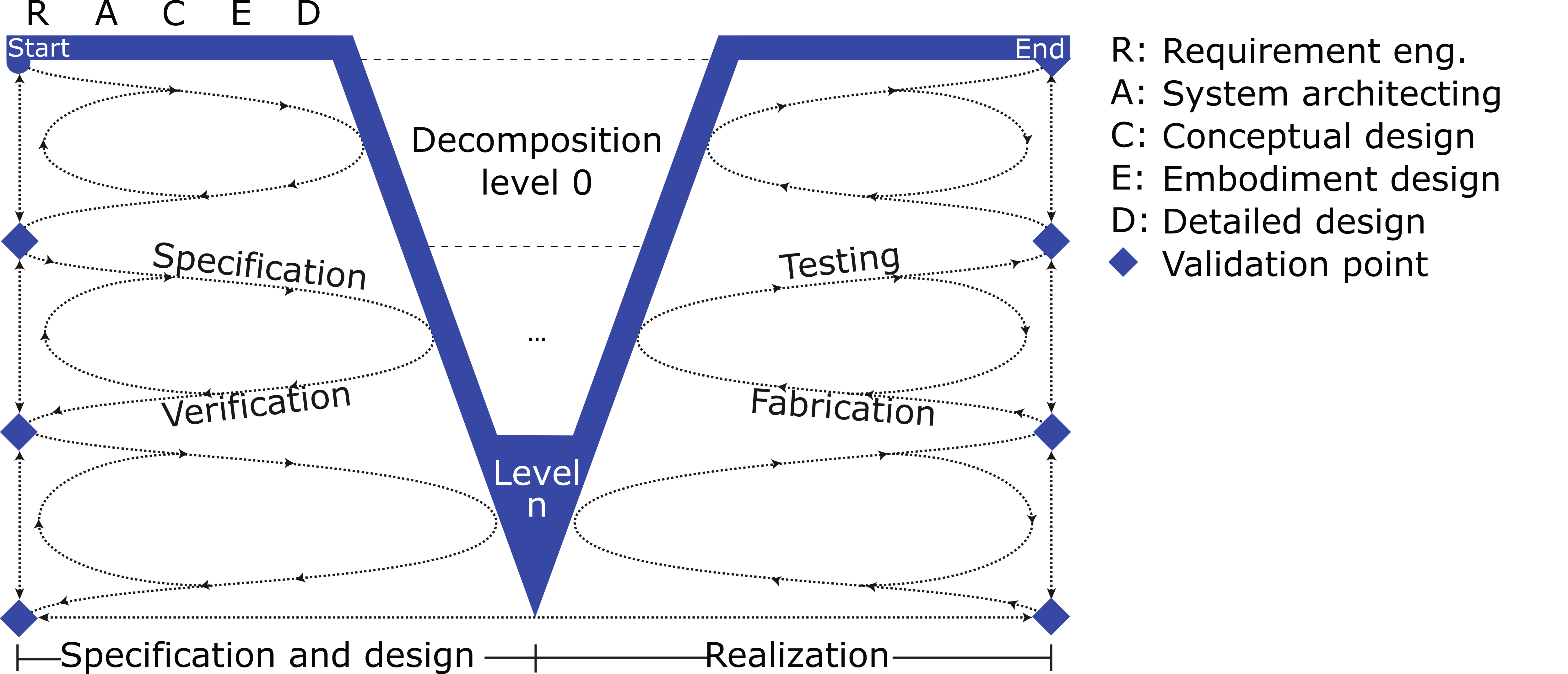
Starting at the top left, the requirements (R) at the highest decomposition level are specified. Next, a basic system architecture (A) is defined that denotes the interactions between the conceptual components. Next, a concept (C), i.e. a working-principle and an embodiment (E) are chosen for each component. During detailed design (D) one aims to verify whether the requirements can be fulfilled given the architectural, working-principle and embodiment choices. If so, the first customer validation point is set to check whether the solution satisfies the customer needs thus far. If not, one has to consider other architectures, concepts and embodiments.
Subsequently, one can move to the next decomposition level at which requirements are specified, the architecture is defined, and the concept (working-principles) and embodiment are chosen and verified for all (sub)-components. This process continues until a sufficient level of detail is achieved to start the realization phase (right side of the V). To ensure proper component integration it is essential to have a proper understanding of the system architecture during all phases and at all decomposition levels of the design process. Lack of understanding often leads to costly and lengthy design iterations.
Classical systems engineering
Systems engineering traditionally advocates the use of separate requirement, function, and component trees, as shown in the figure below. Creating dependencies between these trees is done manually. This is a non-trivial, cumbersome and error prone task, which relies heavily on the good-behavior of the modeler to obtain a proper model. Moreover, the neat requirement and function hierarchies often do not exists in real-life. That is, design decisions made during the project often yield new requirements and new functions, which do not fit within the hierarchical structure.
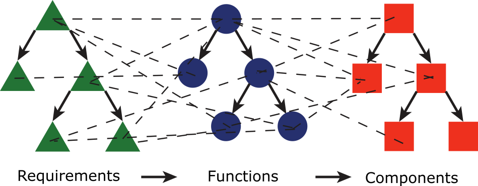
Finally, the primary goal of the resulting network is to ensure traceability of requirements to functions and physical components. Therefore, it does not represent the system architecture.
Ratio methods and tools build upon the system architecture definition of Ulrich and Eppinger4:
Quote
System architecture is the mapping of a system's functions to the physical components within the system, and to the dependencies between those components. -- Ulrich and Eppinger4
Dependency Structure Matrices
In the literature, dependency structure matrix (DSM) methods are commonly used to model, visualize and analyze system architectures in a large variety of industries. The book of Eppinger and Browning5 provides a wide variety of DSM applications in industries and academia alike. A DSM is a square \(N \times N\) matrix in which a non-zero entry at position \((i, j)\) indicates that row element \(i\) depends on column element \(j\). A DSM can displays multiple dependency types and strengths at once. Product DSMs are typically used to model dependencies between components.
The two product DSMs on the left of the figure below display four dependency types between six components. One can highlight the system architecture by re-ordering the matrix using a clustering algorithm. In this case, yielding an integrative (bus) module and two independent modules. This provides opportunities to modularize a system.
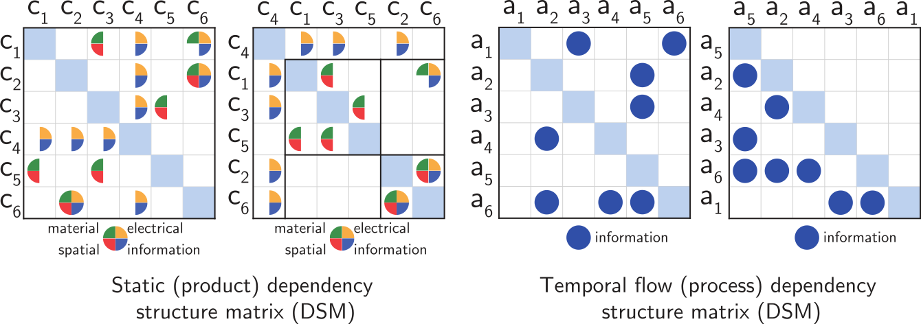
Process DSMs, as shown on the right hand side, are used to model dependencies between functions or (design) parameters. The order of elements along the diagonal of the DSM indicates the sequence in which each element is designed during the process. Sequencing algorithms are used to reduce feedback loops (upper-diagonal marks) which are a source of rework.
The Elephant Specification Language
When systems grow in scale and complexity, it becomes challenging to obtain and maintain an accurate and up-to-date model of the system architecture. Moreover, is is very difficult to ensure the consistency of such a model with the system specifications which are usually written in natural language. To overcome these challenges, Ratio has developed the Elephant Specification Language (ESL) in cooperation with the Eindhoven University of Technology. ESL is specifically developed to enable engineers to write highly structured, multi-level, computer-readable system specifications from which dependencies between requirements, functions, components, variables and combinations thereof can be derived automatically.
In ESL the (functional) requirements are written following a fixed syntax (grammar) within the system decomposition tree, yielding a single structured unambiguous system specification. The ESL compiler performs consistency checks and derives a model of the system architecture. This model can be used to optimize the design and the design process of a system and serves as an interactive visualization of the system specifications.
Where to from here?
- ESL itself is explained in more detail in the Tutorials, How-to guides and the ESL Reference.
- Read more about system specifications at Systems specifications in more detail.
- Read more about why ESL is a useful addition with respect to existing tools at Why ESL?.
- The System architecture modeling and analysis page shows how the resulting dependency network can be used to help structure and coordinate your design process and enable you to improve your design.
-
K. Forsberg and H. Mooz. The relationship of system engineering to the project cycle. In Proceedings of the INCOSE International Symposium, 57–65. Wiley Online Library, 1991. ↩
-
B. W. Boehm. A spiral model of software development and enhancement. Computer, 21(5):61–72, 1988. ↩
-
G. Pahl and W. Beitz. Engineering design: a systematic approach. Springer Science and Business Media, London, England, 2007. ↩
-
K. Ulrich. The role of product architecture in the manufacturing firm. Research Policy, 24(3):419–440, 1995. ↩↩
-
S. D. Eppinger and T. R. Browning. Design structure matrix methods and applications. MIT press, Massachusetts, USA, 2012. ↩